
Blog
Precision Landing Using Fiducial Markers
Lead Engineer: Abhishek Shastry
This project aims to develop a precision landing system for eVTOLs using fiducial markers.
What is a fiducial?
Fiducials are custom patterns that can be quickly and reliably detected in camera images using conventional computer vision algorithms. They are similar to QR codes but differ in the aspect that for QR codes to be detected the camera has to be close and near normal to the surface to which the code has been printed. Fiducials, on the other hand, are designed to be detected from much larger off-normal (slant) angles. QR codes are used to encode and convey information, while fiducials are used for navigation. They specifically provide pose (position and orientation) estimates of a flat surface from a camera. Although, a fiducial design with encoded information is theoretically possible, such designs come at the cost of navigation performance.
Figures: six Fiducials (above); QR code (below)

FAA recommended vertiport design

Reference Vertiport Design by FAA
TLOF (Touchdown and Lift-Off area): Load bearing area within which the landing gear should be at touchdown
FATO (Final Approach and Take-Off area): Entire Aircraft should be inside this area during the VTOL landing maneuver
Safety Area: Safety margin for aircraft that might diverge from FATO
CD (Controlling Dimension): Diameter of the smallest circle that encloses the aircraft when projected to a flat surface
The technology will come into play only in the final phases of an aircraft landing. It is assumed that the technology used for en-route navigation (such as GPS or MBS or visual maps) can safely navigate the vehicle until the final stages. The precision landing technology will then guide the vehicle with sub-cm level accuracy to the center of the vertiport.
Reference Descent and Landing trajectory for Supernal vehicle
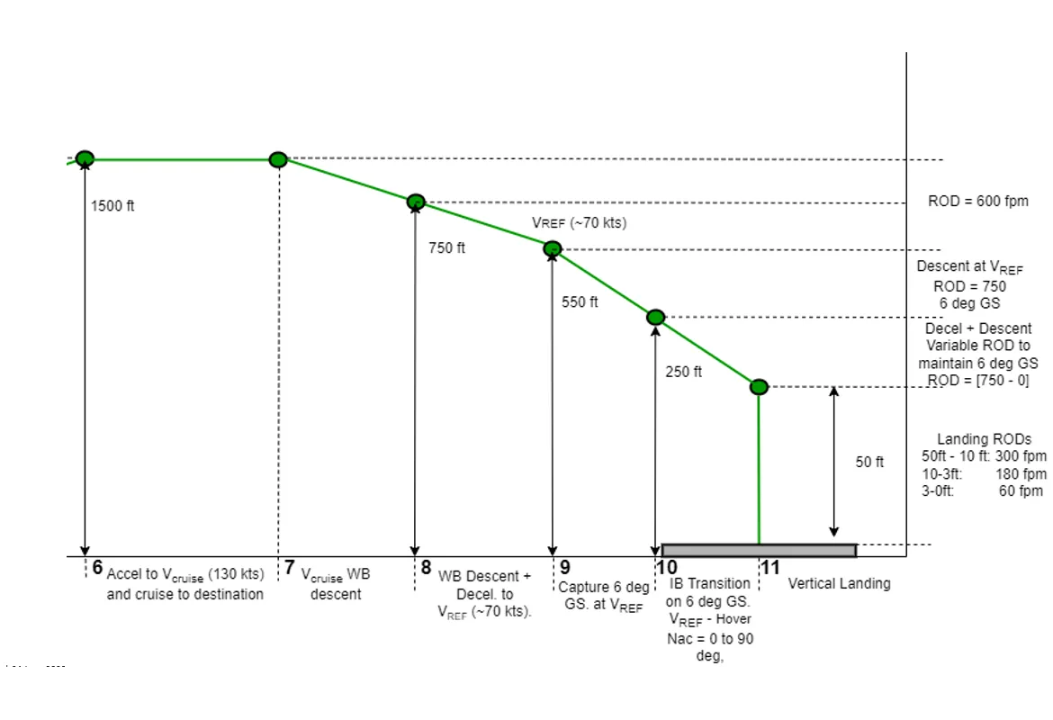
Figure: Expand image
Minimum elevation angle for fiducial detection:
Our lab experiment shows that the absolute minimum elevation angle from which the fiducial can be detected is 8 degrees. Even at this elevation, the detection rate is very low at 2-3 Hz, and moreover the camera has to be close to the fiducial. This is primarily because at such low elevation, the 2D square fiducial collapses to a 1D line. For the fiducial to be detected at large camera-fiducial distance, and at reasonable detection rate (>10 Hz), experiments showed that the minimum elevation should be 20 degrees.
A Physics based constraint:
The plot below shows the variation of elevation angle of the aircraft against changes in its altitude, when the aircraft is travelling on the 6-degree glideslope path. From the plot, 20-degree min elevation angle means 70 ft. max vertical altitude from which the fiducial can be used. This essentially constrains the fiducial based landing method to regions close to the vertiport. For regions farther away from the vertiport, it can be argued that glide slope is the only parameter that the aircraft needs to know to maintain the correct approach trajectory. Hence, for those regions, technologies such as PAPI lights, or GPS+WAAS or GPS+GBAS or ILS should be used.

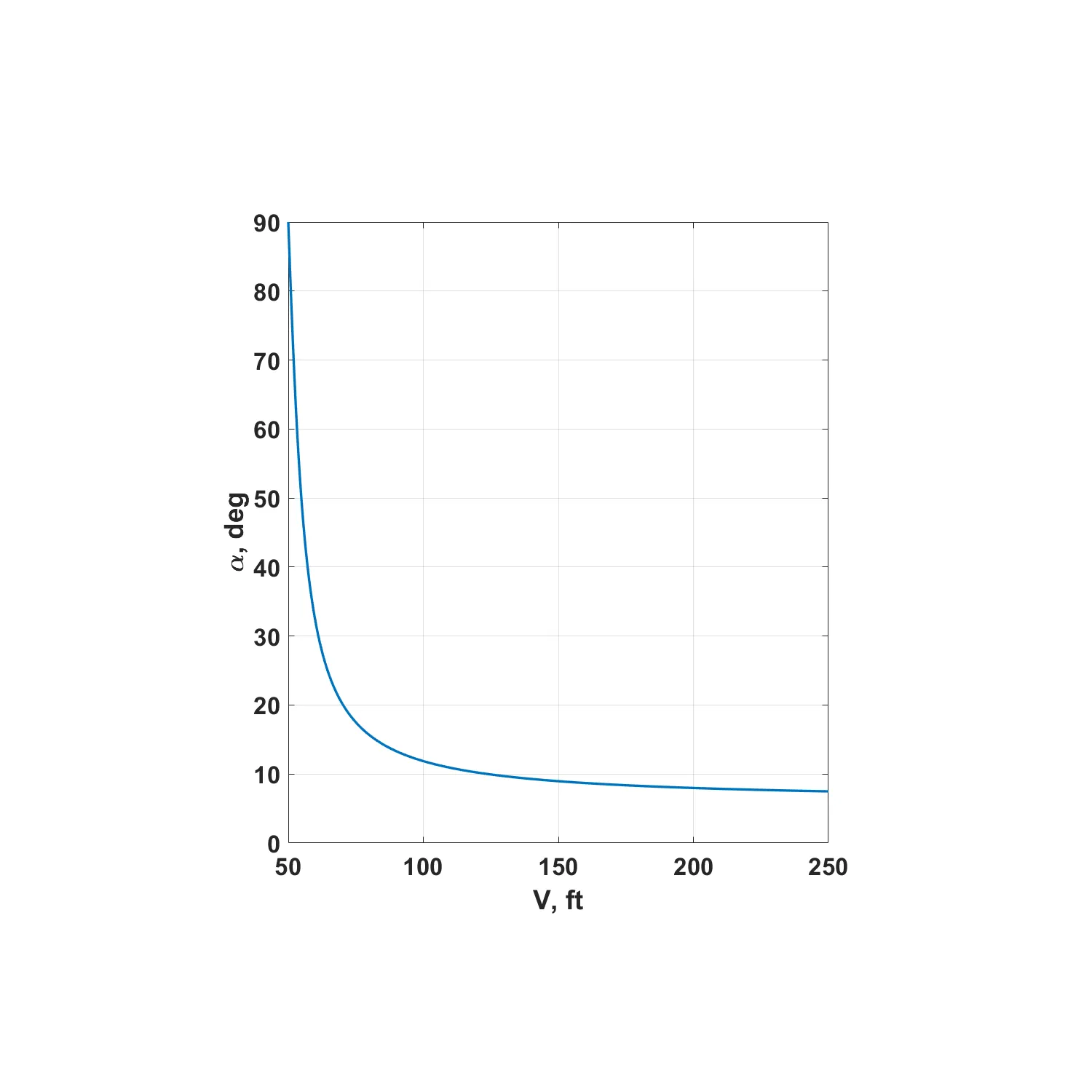
Figure: Variation of aircraft's elevation with changes in its altitude when it flies on the final part of descent and landing trajectory. Expand image
Why Precision landing?: Because of Safety and fuel.
The vehicle transitions from fixed wing to VTOL mode in this final stage. Power consumption in VTOL mode is approximately 10 times higher. Hence, the vehicle needs to be able to precisely navigate with respect to vertiport in the final stages, so as to come to exactly dead center above the vertiport and descend along the centerline to touchdown. Any correction/go-around maneuver will be costly from fuel consumption perspective. In addition, the precise landing maneuver improves safety, especially in dense urban areas.
Certification:
This technology will act as a precision guidance system for the pilots while landing. Pilots can use it to control the vehicle to the dead center of the vertiport and then descend precisely along the centerline. For future capabilities, it can be used for the auto land feature. Hence the technology must be certified to DAL-D or DAL-C for use on the EIS vehicle and to DAL-B/DAL-A for future use.
But what about Fog?:
The primary effect of fog is a reduction in visibility, typically below 1 km (3280 ft.). It is then when the ILS system is required for conventional airplanes. As per FAA, Cat I ILS is used when fog is greater than 800 m. At a cruise altitude of 500 m./1500 ft., an aircraft should be able to safely land in Cat I fog. In Cat II the visibility drops to 400 m. In this case too, the fiducial should be visible to the onboard camera as the system kicks in only at 250 ft. or 76 m. In Cat IIIa visibility drops to 200 m, and in IIIb to 50 m. So, the system would still work in even Cat IIIa fog. It's only in CatIIIb fog that it would start to have some problems. Hence, the system should still work in most fog conditions.
Fog tests:
We did lab testing in fog/low-visibility environment to evaluate how the fiducial performance would degrade in these scenarios.
Largest possible fiducial design covering the entire vertiport

This is the largest fiducial design we can reasonably hope for at the vertiport. It preserves the broken wheel markings that FAA proposed in the TLOF area, and covers the entire vertiport. The outermost dimension is 3.2 CD. This large fiducial can ensure its visibility from distances as large as 1500 ft., although while being still within the 20-degree elevation limit.
With regards to the camera system, minimum of two fixed focal length cameras are proposed for the project. A 120-degree field of view (FOV) for the Vertical landing phase and a 60-degree zoom camera for the approach phase. The 60-degree fixed zoom camera can be replaced with a (10-60 degree) variable focal length camera if depth of field becomes a problem.
Large scale fiducial manufacturing:
For FTB tests, a large fiducial (approx. 50 ft. x 50 ft.) will be needed. This is currently planned to be painted on a flat platform made from I-trac tiles.

Sample I-trac tile
TIle Size (in.): 47.5 (L) x 36.3 (W) x 2.1 (H)
Weight Per Tile (lbs.): 38
Area Per TIle (sq. ft./pc): 8.47
Static Compression Capacity (lbs./sq. ft.): 86,400

Sample 5 ft. x 5 ft. fiducial painted on a small platform made from I-trac tiles